bc10
Summary †
The serial console of bc10 can be connected to the 30-pin connector. Communicating with a PC,
the serial console is useful. However, to utilize the serial console, an interface adapter is required.
This section introduces two examples of how to make a serial interface.
Serial Interface †
Example 1 †
List of Parts †
- Wires (Recommend 0.26mm diameter single wires for connections)
- Protoboard
Connectors †
- J1 iPod Dock connector 30pin (Male)
- J2 EIA-574 connector (Female)
- Connected by straight cable (Null modem)
- J3 PIN HEADER(10pin)
- BeagleBoard (IBM PC mother board) equivalent. The converter for PC is usable, but if do not use it,
do not need to put this PIN HEADER on the universal board.
Circuit Schematic †
How to Assemble †
- At J1 connector, a GND (#1, #2, #11, #15, 16, #29, or #30 pin), 3.3V (#18 pin), Tx (#12 pin), and
Rx (#13 pin) are soldered to the wires
- According to the circuit schematic, put MAX3232, ceramic capacitors, and J2 on the protoboard
- Connect J1 to the universal board
- Test the functionality of serial interface
- EIA-574 is Null modem, so it can be connected to a RS-232C (straight and 9 pins)
- To communicate the device, the settings of terminal software at the host PC are shown below
- Speed:115200bps
Data length:8bit
Parity:None
Hardware Flow:None
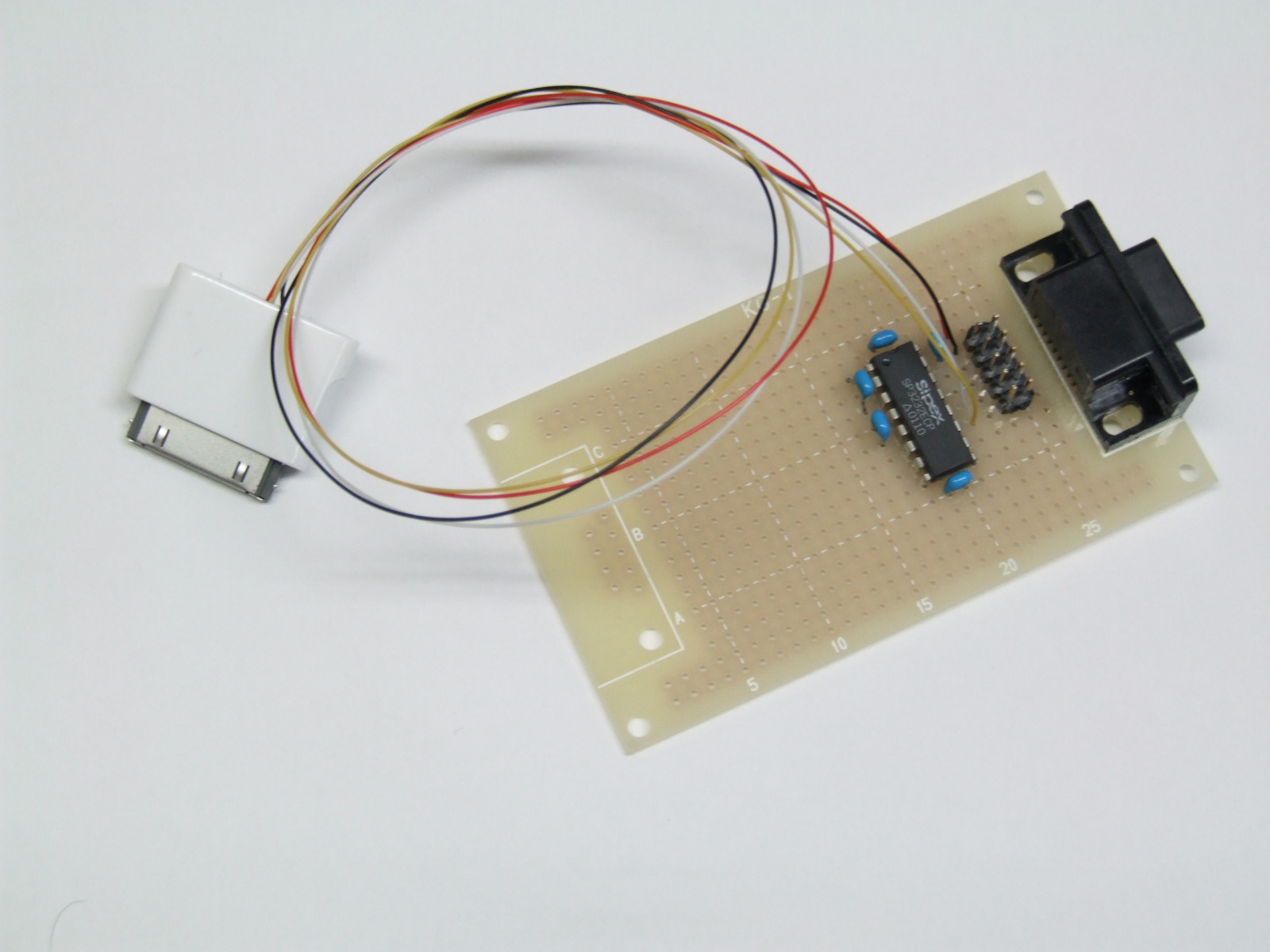
Exterior †

Example 2 †
List of Parts †
How to Assemble †
- Break a set of PIN HEADER (1 set for 40-pin x 2 lines) into 2 sets of 15-pin x 2 line.
- Solder the resized PIN HEADER into iPod interface board. Make sure the direction that the iPod interface
board is attached to bc10, and be careful with the soldering side of the iPod board.
- According to the circuit schematic, place RS232C on the universal board.
- iPod 30pin (J1) is replaced with the 2 lines of the resized 15-PIN HEADER.
- Since the iPod interface board is connected to ribbon cable later, do not confuse the pin numbers
on the iPod interface board.
- PIN HEADER 10p (J2) is only used when bc10 is communicated by the serial communication cable for
BeagleBoar. Otherwise, it is not necessary.
- J3 primarily uses the female side. Its cable is Null modem and the connection is cross. To use straight cable,
it can be connected to a PC serial port.
- When the male side of J3 is used, the 2nd and 3rd pins are exchangeable. As it is connect to PC, use cross
cable.
- 30pin connectors are crimped with both edges of the 30-way ribbon cable. Pay attention to pin numbers and the
directions of the connectors.
- iPod interface board and the protoboard, which is equipped with RS232C interface, is connected. This is the
end of the assembly process.
- 30pin connector works well as it is connected only 4 required lines, and other connections can be skipped. GND
is needed to only one connection out of seven GND connections. The selection is arbitrary.
Others †
- Several chip makers produce clones of MAX3232, and the clones work fine and can replace the original here.
- EIA-574 connector can be used for not only board-type but also cable-type. Depending on PC environment, freely
set up the connector.
- EIA-574 is the standardized name for DSub-9pin type of serial communication.
|
![[PukiWiki] [PukiWiki]](image/bc_logo.png)