bc10/Hardware
Overview †
bc10 does not include JTAG in the set. Users need to make own JTAG for bc10. This section explains how to make a JTAG for
bc10. The example of JTAG consists of several parts: JTAG board, JTAG adaptar board, and cable. JTAG board, The Flywatter,
and JTAG Adapter Board, a part of BeagleBoard Adapter Kit are produced by by Tin Can Tools and these are commercial
products for BeagleBoard. Users need to work on JTAG cable. The JTAG connector of bc10 does have the same pinning as
BeagleBoard's, but the size of bc10's JTAG connector is differ from BeagleBoard's. This section explains how to make the cable.
JTAG board †
Flyswatter †
The JTAG board is called Flyswatter, which bridges between bc10 and the host computer. This is connected to the host via USB and
attached to bc10 via a 14-pin bc10 specific JTAG cable. Flyswatter is also designed as a debugger, and it supports OpenOCD.
JTAG Adapter Board †
JTAG Adapter Board is part of BeagleBoard Adapter Kit. It provides the 14-pin JTAG interface to the Flyswatter, and it is connected
to the bc10 specific JTAG cable.
bc10 Specific JTAG Cable †
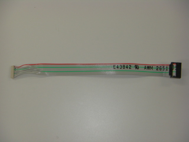
The pin order of bc10's JTAG connector is the same as BeagleBoard's. However, due to the design of bc10, bc10 uses the
different size of JTAG connector from BeagleBoard. This prohibits using the commercially available JTAG cables. The
instructions of how to make the JTAG cable for bc10 are shown below.
Parts Table †
Instructions †
- Split an edge of the ribbon cable 40mm deep.
- Push the split ribbon cable into the connector contact with equal force.
- From the first pin, the pins of the connector contact are orderly placed into the connector socket housing one by one.
- The other end of the ribbon cable is pushed into the connector contact. The location that each pin is placed is needed
to be the same as its corresponding pin is originally put at the other end.
- This is the end.
The Picture of Example Cable †

Pin Assignment †
| No. | Signal | |
| 1 | JTAG_TMS | |
| 2 | JTAG_nTRST | |
| 3 | JTAG_TDI | |
| 4 | GND | |
| 5 | Vcc | 1.8v |
| 6 | NC | |
| 7 | JTAG_TDO | |
| 8 | GND | |
| 9 | JTAG_RTCK | |
| 10 | GND | |
| 11 | JTAG_TCK | |
| 12 | GND | |
| 13 | JTAG_EMU0 | |
| 14 | JTAG_EMU1 | |
Revision History †
2010/10/12 The article is initially uploaded.
![[PukiWiki] [PukiWiki]](image/bc_logo.png)