bc10

Serial

This is the information of how to apply the 30-pin breakout to the 30-pin connector, which is located at the lower part
of bc10.

Design

Assembly

  • Parts-list
    Product NameMakerProduct Serial NumberQuantityMemo
    1RS232C Line Driver ICMAXIMMAX32321There are a lot of clones. Please select for a 3.3V Line Drive IC. 5V one is not acceptable
    2Multilayer Ceramic CapacitorMurata Manufacturing0.1μF5it can be replaced with any 0.1μF ceramic capacitors
    3DSub 9-pin connector (female)1http://akizukidenshi.com/catalog/g/gC-00645/ and others (The information at the link site is in Japanese)
    4Pin Header1Pin Header in 2.54mm Pitch. This is needed for 30 pins.
    530-pin connector for iPod1This is available at here. The product information is written in Japanese. Please use the picture of the product as a reference
    5Small Signal Connector Housing14x2 total 8 pins
    6Small Signal Contact4
    7Signal Cable20~30 cm approx.4 wires
    •Many manufactures produce the compatible products and/or clones of RS232C Line Driver IC “MAX3232”. These
    products can substitute the original. Be careful, 3.3V products can be used here. Some of clones are 5V, and the
    5V clones cannot be applicable here.
  • How to Make

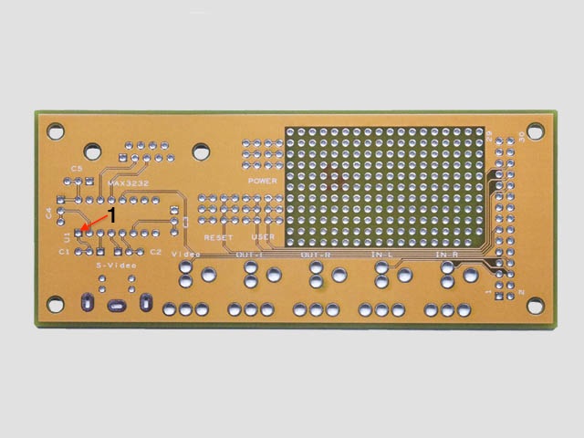
    1. MAX3232 is placed on the breakout. The square-land (U1) indicates the location, where the first pin of IC
    is placed.
    30pinbkout64x48.jpg

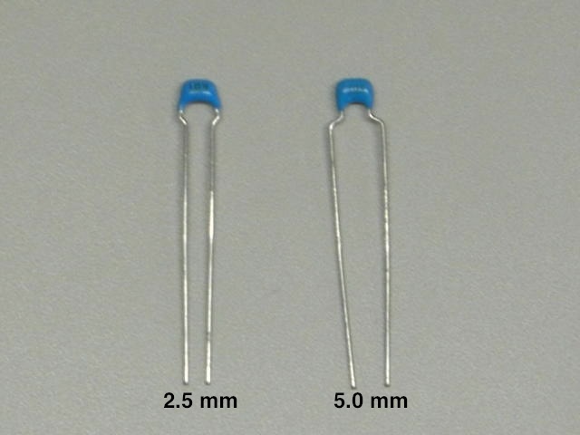
    2. Five Multilayer Ceramic Capacitors are put into the breakout.
    At each location, there are one square-land and two round-lands, and it requires only one square-land and one
    round-land. A round-land can be selected depending on a shape of capacitor. If use a 2.5mm-multilayer ceramic
    capacitor, choose the round-land next to the square-land. As using a 5 mm-capacitor, skip one round-land and
    apply the far side round-one. This makes ceramic capacitors apply to the breakout effortlessly and smoothly.
    CIMG8702n.JPG

    3. Apply DSub 9-pin connector.

    4 Place 30 pin headers. Remove the 17th-pin. (Please see the picture 4)
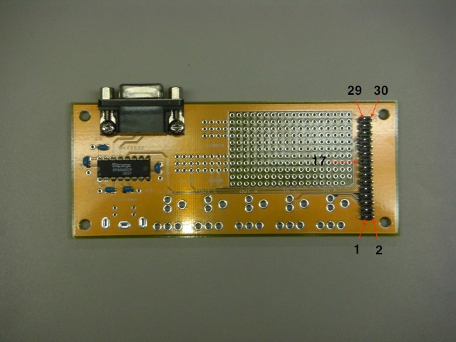
    CIMG8711n.JPG
    This is the end of working on the breakout.

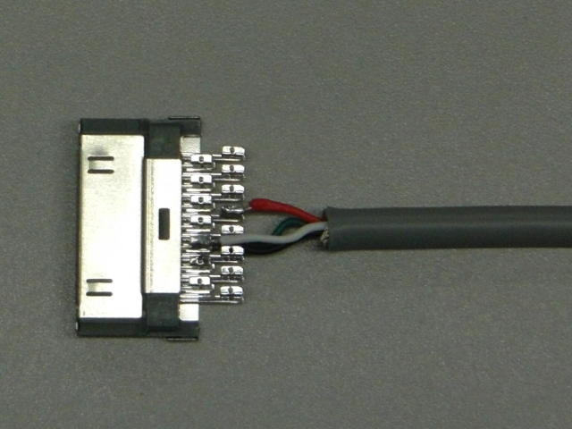
    5 Make a cable. Connect a four-wire cable to 30-pin iPod connector. Use only four terminals of 30-pin iPod
    Connector. #11, #12, #13, and #18 terminals are connected to black, white, green, red cables, respectively.

    terminalWire Color
    11black
    12white
    13green
    18red

    CIMG8705.JPG

    6. On the other side of cable, small signal contacts are attached.
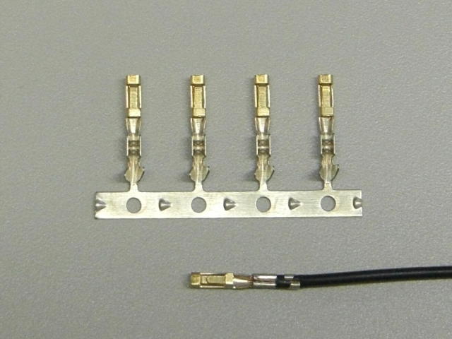
    CIMG8733.JPG

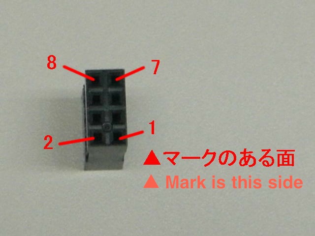
    7.The small signal contacts are inserted into the small signal connector housing. The wires, which are connected
    to #11, #12, #13, and #18 of 30-pin iPod connector, are linked to #1, #2, #3, #8 of terminals of the small signal
    connector housing, correspondingly.
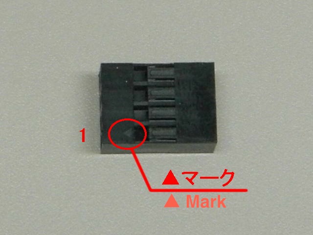
    CIMG8729.JPG CIMG8730.JPG
    The small signal connector housing is 4x2 and has 8 terminals. These terminals are connected to #11, #12, #13,
    and #18 pins of pin headers on the breakout, respectively. If the wires are too thin, the small signal contacts
    could not hold wires well. Please change the wires more thicker than the the originals.
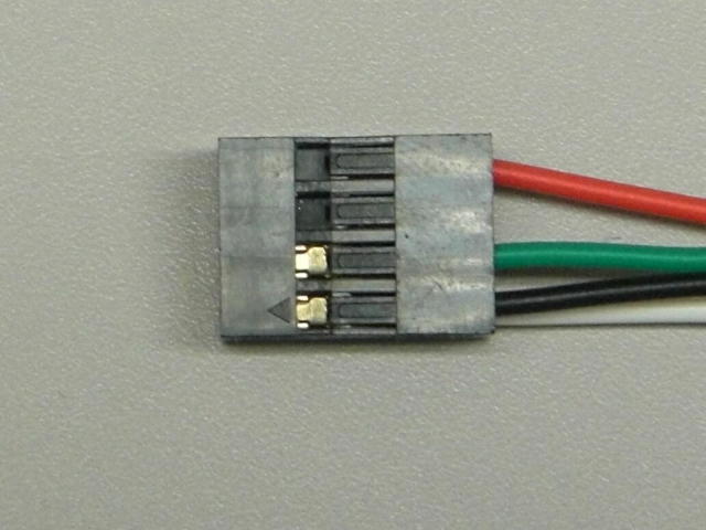
    CIMG8731.JPG

How to Use

  • Connect the cable created above to the 30-pin connector at bc10. The 30-pin iPod connector is attached to the 30-pin
    connector of bc10.
  • Connect the small signal connector (4x2, 8 terminals) to #11~18 pins of the pin header on the breakout. To turn the black
    wire (#1, connected to #11 pin) toward #1 pin side, make sure that red wire (#3, connected to #12 pin) is put next to the
    black one.
  • Attach a relay cable at the side of Connect Dsub 9-pin. Connect the cable to RS232C. At the other side, connect to a serial port
    of a PC.

Memo

  • This example uses only the serial console communication function of this breakout. This breakout is capable of handling other signals and
    can be equipped with other functions.
    • USER button
    • RESET button
    • Power supply switch
    • Stereo Audio input/output
    • Video/S-Video output

Revision History

  • 2010/11/10 This article is initially uploaded.
  • 2010/11/12 Add more pictures.

Attach file: fileCIMG8733.JPG 1687 download [Information] fileCIMG8731.JPG 1685 download [Information] fileCIMG8729.JPG 1775 download [Information] fileCIMG8730.JPG 1836 download [Information] filebc10-009-0001_brd.pdf 1860 download [Information] fileCIMG8711n.JPG 1864 download [Information] fileCIMG8705.JPG 1822 download [Information] fileCIMG8702n.JPG 1817 download [Information] filebc10-009-0001.zip 1485 download [Information] filebc10-009-0001.pdf 2080 download [Information] filebc10-009-0001.dsn 1544 download [Information] file30pinbkout64x48.jpg 1809 download [Information]

Front page   Edit Freeze Diff Backup Upload Copy Rename Reload   New List of pages Search Recent changes   RSS of recent changes
Last-modified: 2010-11-12 (Fri) 11:25:45 (5346d)