bc10
Breakout †
This is the information of a Breakout board, which is connected to Main Board of bc10 via a slot for Expansion Board.
This Breakout is attached to the left side (from AMOLED) slot of Main Board, which is the other side of slot that the
standard (included) Expansion Board is connected.
- Design
- Schematic and Gerber data
- Parts List
| Product Category | Product ID Number | Maker | Quantity | Memo | | Connector | 14 5078 030 510 861+ | KYOCERA ELCO | 1 | |
Sample #1 (Barometer sensor) †
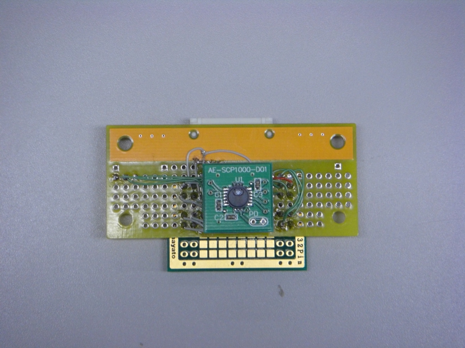
The barometer module, AE-SCP1000-D01, is used for this sample.
- Schematic
 bc10-002-0003.pdf bc10-002-0003.pdf
The schematic is only available. Since no boards are created for this sample, there is no Gerber data.
- Description
The barometer module works between 2.4~3.3V (standard 2.7V), and the outputs of this module can be read via
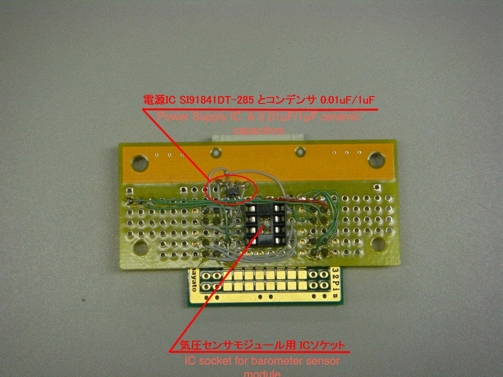
SPI connection. For this sample, the 2.85V output LDO (Low Drop Output) type Power Supply IC (S191841DT-285)
is selected. If output voltage (including the margin of error) is between 2.4 and 3.3V, the original IC can be replaced
with other makers' ICs here. (To use other power supply ICs, be careful with voltage drop, too.)
※ For bc10, 3.3V output includes the margin of error, and occasionally its output voltage exceeds 3.3V. This excess
voltage highly unlikely causes malfunctions on this barometer module. To meet the guideline of the data sheet,
use this Power Supply IC and reduce the voltage at 2.85V.
The digital interface of bc10 is 1.8V level, and this module cannot directly connect to bc10. (As directly connecting the
two devices, it may cause damages on bc10.) To connect these devices, the signals are needed to be transferred between
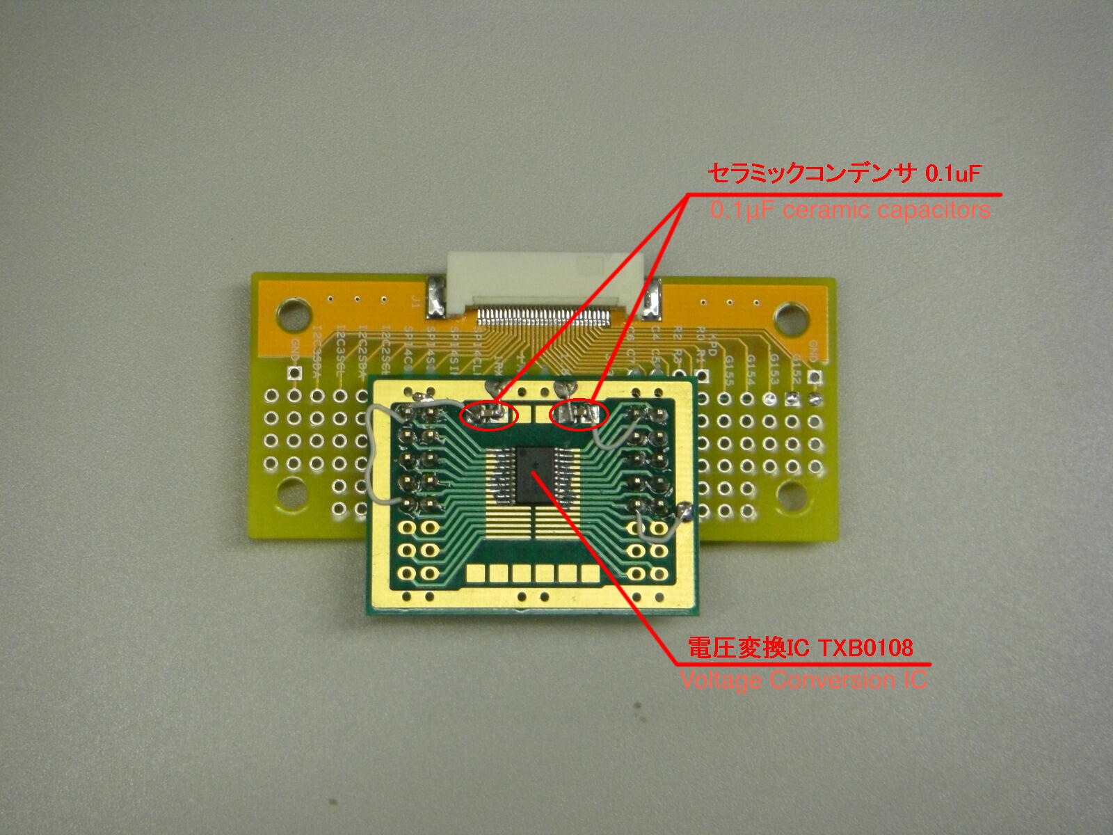
1.8V and 2.85V. For the connection, a Voltage Conversion IC, TXB108 is employed. As this IC is only capable of surface
mount, a pitch converter board is used for mounting this Voltage Converter IC.
bc10 and the barometer sensor module is attached via a the voltage converter. 4 lines of SPI (CLK. MOSI, MISO, and CS)
and one line of TRG and DRDY (totally 2) are connected. The latter 2 lines are connected to 2 lines of GPIO (GPIO_152
and GPIO_153, respectively).
On the sample, the empty pins are remain open. There are no issues for experimental level, but to use the device in far
more stable condition, pull-up resistors can be applied.
- Parts
- 0.01μF and 1μF ceramic capacitors are for using the Power Supply IC S191841DT-285. If other makers' IC is used,
please study its recommended circuit, first.
- Pin Headers are divided into 2 groups (2x5) and used.
- Instructions
Go through whole assembly process before actually start working on the board.
- Each part is placed where is should be, and examine the layout and the order of wiring.
- Wire the Power Supply IC (S191841DT-285) at empty space of the universal pattern. Gaps between IC pins are narrow,
so that please be careful with short circuit. To use the pitch converter board, easily wire it on.
- The IC socket, which is attached to the barometer module, is mounted. Wires keep longer as each wire pulls out from the pin.
- the voltage converter IC is mounted on to the pitch converter board as using Pin Headers.
- Wire each connector.
- Mounted Side 1
–- Mounted Side 2
- The Barometer module is mounted
- To test the operation
This is a shell script for testing its operation. This shell script controls SPI and GPIO.
 scp1000_test.sh scp1000_test.sh
Sample #2 (Thermometer sensor) †
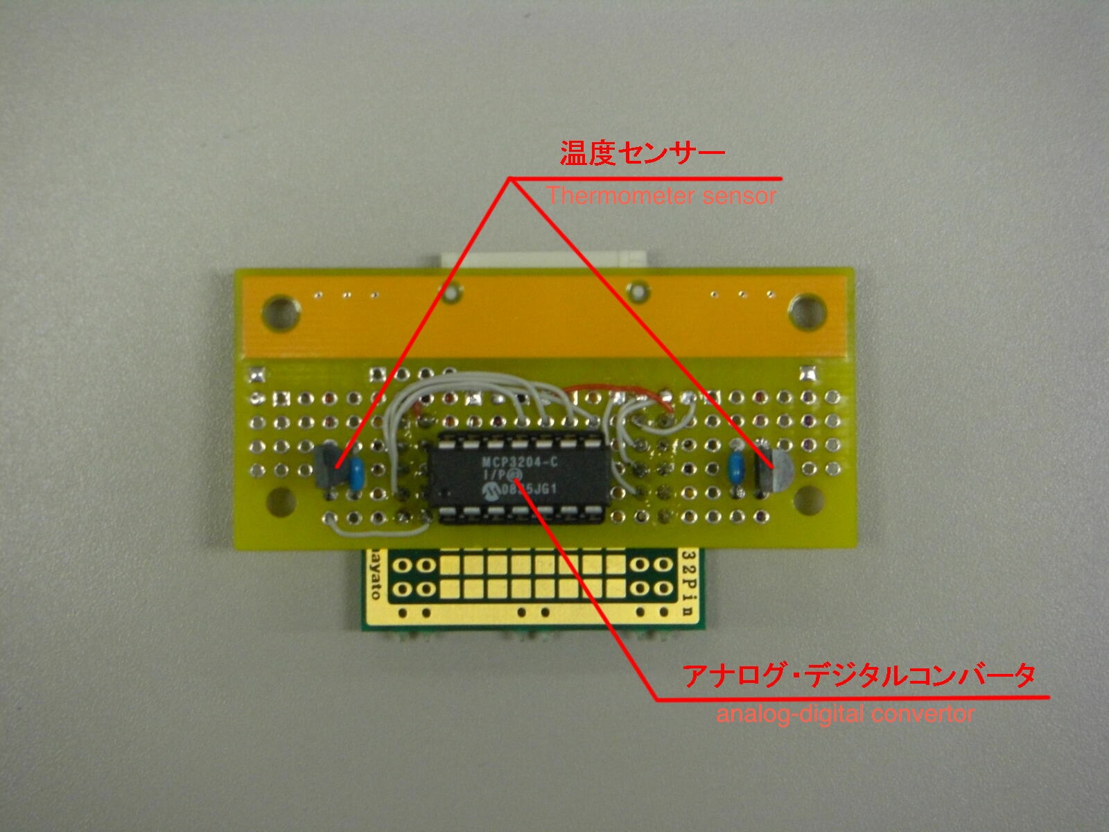
A thermometer sensor and an AD converter are used for this sample.
- Schematic
 bc10-002-0006.pdf bc10-002-0006.pdf
The schematic is only available. Since any boards are not created for this sample, there is no Gerber data.
- Description
The thermometer sensor is an analog output type sensor, which changes the output voltages proportional to temperatures.
It outputs 10.0mV per 1 degree Celsius, and it can measure from 0 to 70 degree Celsius (accuracy of 4 degree Celsius).
Since the expansion board connectors of bc10 do not have analog input interface, analog outputs must be converted into
digital values via an analog-digital converter. Both thermometer sensor and analog-digital converter work between
2.7~5.5V, and bc10 provide power to the sensor and converter at the level of 3.3V. On the other hand, the digital interface
of bc10 requires at level of 1.8V, so it cannot connect directly. (If the direct connection may cause significant damage on bc10.)
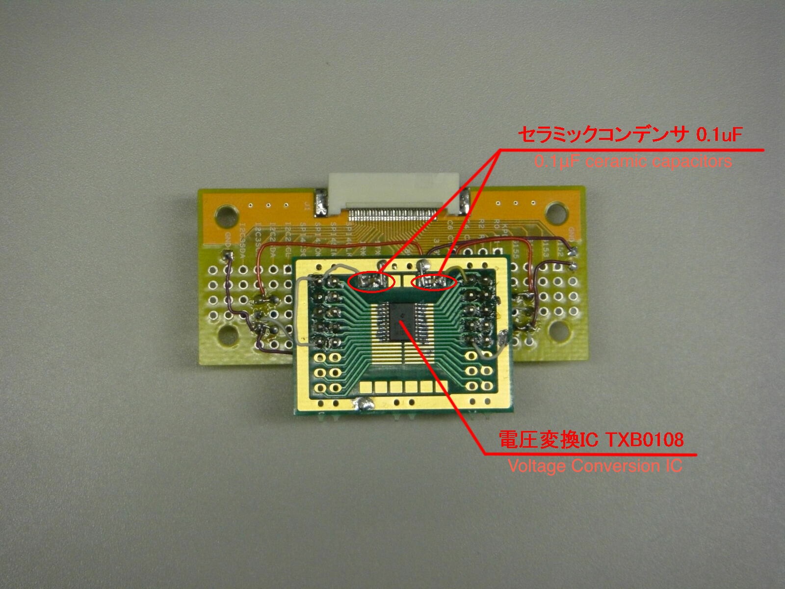
To connect these devices, the signal is needed to transfer between 1.8V and 3.3V. To do voltage conversion, TCB0108 is used.
This IC is not surface mount type, and a pitch converter board is used for mounting this voltage converter IC.
As long as keeping pairs A1~A8 with B1~B8, a pair can be replaced with the other pair. 1.8V is placed at A-side,
and 3.3V is always on B-side. bc10 and the analog-digital converter are connected via the voltage conversion IC.
4 lines of SPI (CLK, MISI, MISO, and CS) are occupied.
On the sample, the empty pins are remain open. There are no issues for experimental level, but to use the device
in far more stable condition, pull-up resistors can be applied.
- One package of the thermometers contain 8 thermometer sensors. In this sample, there is extra space
in the expansion board, two thermometer sensors are used. There are no problems with using 1 sensor.
(As using 1 thermometer, four (4) 0.1μF-ceramic capacitors are required.)
- In this sample, both ceramic disk type and surface-mount chip type ceramic capacitors are used.
- The pin-headers are divided into 2 sets of 2x5 size.
- The data sheet of analog-digital converter is available at Mirochip Technology Inc's website.
This site is highly recommended for a reference.
- Instructions
Please read through whole section carefully before start working on.
- Each part is placed where is should be, and examine the layout and the order of wiring.
- The IC socket for the analog-digital converter and ceramic capacitors are placed.
- The thermometer sensors are put into the place.
- Wire placed parts. The wires, which are going to attach the analog-digital converter are kept longer. These
wires are connected to the IC socket. Reminder that the voltage converter IC will be mounted and wired later,
and keep enough room for mounting the voltage converter IC as mounting the parts described here.
- Mount the voltage converter IC on the pitch converter board. The pitch converter board are connected to the
Pin Headers, which are on the expansion board.
- All connectors are wired.
- Mounted Side 1
- Mounted Side 2
History of Revision †
- 2010/10/28 This article is initially uploaded.
- 2010/11/29 The samples are added.
|
![[PukiWiki] [PukiWiki]](image/bc_logo.png)