bc10
Outline †
This is the outline of how to assemble bc10. The list below describes how to place Main board, AMOLED, and other parts into the enclosure.
- This introduces how to connect between Main board and expansion boards. As connecting the left side expansion board to Main board, please handle the power cable gently.
- Attach the camera module on Main board.
- Put AMOLED into the upper case, and fix it on the case by the small plastic parts. These small plastic parts are need to be placed in the certain direction. Please be careful.
- AMOLED, which is in the upper case, is attache to Main board. As connecting AMOLED and Main board, please carefully insert the flexible of AMOLED into the connector of Main board. If this process is mishandled, the picture does not appear on AMOLED.
- Main board is fixed onto the upper case. Please carefully tighten up screws. If it is tightened too hard, it may become a cause of issues.
- Please tapped the power supply to a electricity outlet, and turn on the switch of bc10. Make sure that bc10 works appropriately. To test the working condition of bc10, highly recommend to use the terminal of the host PC.
- Confirming that bc10 is working supposedly, close the bottom case and fix it. Do not tighten the screws too hard.
Instructions †
1. Connecting Main board and the expansion boards †
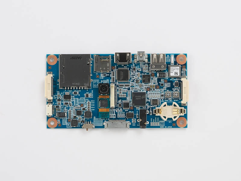
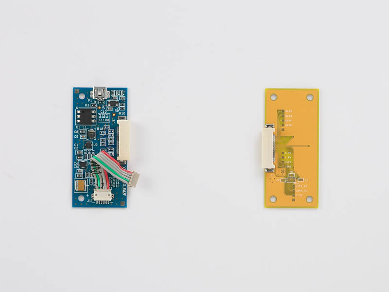
Main board (Picture:below-left) is connected with the expansion boards (Picture:below-right).


In the picture of the expansion boards, the left (blue) one is called “the standard expansion board with power supply”, and the right (yellow) one is called “the standard expansion board with breakout.” These standard expansion boards is capable of handling keypads. “The breakout expansion board,” which is available as an option, does not work with keypad.
The standard expansion board with power supply is connected to the left side expansion slot on Main board. Make sure that the power supply cable is connected between the expansion board and Main board.
If the supply cable is not connected, please insert the cable to the connectors. The details are shown blow. (The cable in the picture is preproduction, the color of the cable could be different from the production model.)
As inserting the power cable to the connector on Main board, please check the shape of the connector and receptor, and gingerly insert it to connector. If the cable, connector, and/or receptor are damaged, it will causes several issues on bc20. Please handle it carefully and gingerly.
The connector of cabler is attached to the receptor on Main board.
The expansion board is also attached to Main board.
2.Connecting camera module †
The camera module is shown below. The connector, which is located the other side of lens, is attached to the receptor on Main board. Please do not the lens. If you touch it with fingers, you may leave the finger prints and dust on the lens.
3.Installation of AMOLED †
As shown picture below, the upper body is placed as front side down, and the top of body is close to you.
AMOLED is put down inside the upper body. As installing AMOLED, the flexible cable comes out to near side (closer to you).
Place the springs (v-shaped plastic parts). To hold AMOLED, the dot of the spring is put toward AMOLED side.
Comb-shaped holders is used for fixing AMOLED. Both edges of a holder is placed into little dots.
Then, keypads are placed. There are no up and down sides of this keypad.
4.Connecting AMOLED and Main board †
Open receptor for the display device, and insert the connector of AMOLED to the receptor. You should insert the flexible cable evenly gingerly toward the end. If the cable is not inserted evenly, the display does not work as bc10 is booted.
The latch at the receptor may be little tight. Please handle it carefully.
The latch is need to be open up as much as it is supposed to be.
To placing Main board on the upper body, the dots guide the location of Main board. The dots are helpful to identify the location, which Main board is placed in.
As shown below, sometimes, the holders of AMOLED often move. As it happens, fix the location of AMOLED first, then, place Main board into the upper body.
5.Fixing Main board on the upper body †
Self-threading screws are driven into the upper body of bc10. The self-threading screws are set vertically on bc10and you have to rightly hold bc10.
There are no screw cutters on the body of bc10. The self-threading screws are actually creating screw cutters. If the pressure is added from the side, the body may be damaged. Also, if these screws are too tight, screw cutters become lose and they could not hold well.
6. Testing bc10 †
As Main board is fixed, please test bc10 at this point. If the bottom plate is closed before testing bc10 and it were something wrong, open up and close the body again. It may damage on screw cutters. Once Main board is placed, attaching serial connection and inserting a SD card, please boot bc10 with Android and other OS your choice.
7. Attaching the bottom †
If there are no issues on bc10, the bottom plate is fixed with self-threading screws. To check the adequate level of tightness, you make sure that the bottom plate is closed appropriately and that the screws do not make any sound as you gently shake bc10.
This process also uses the self-threading screws. As you apply a screw to the body of bc10, you screws in it vertically. If screws are applied slantingly, the body of bc10 may be damaged. Also, if you tighten the screws too hard, you may damage the screw cutters. As the screw cutters are damaged, the bottom plate can not be close and it will be too lose.
This is the end of the assembling process.
Finish †
Front
Rear
These are the pictures of assembled bc10. Body color may differ from yours since this body is a per-production model.
Revison History †
2011/03/02 This article is initially uploaded.
![[PukiWiki] [PukiWiki]](image/bc_logo.png)