![[PukiWiki] [PukiWiki]](image/bc_logo.png)
![[PukiWiki] [PukiWiki]](image/bc_logo.png)
This article provides the step-by-step explanations for how to build a firmware form its source code, then how to write the firmware into PIC of BC-USB-Kit.
When you write your firmware into your BC-USB-Kit, please apply this method.
To complete the build and writing processes, the hardware and applications are required.
- BC-USB-Kit
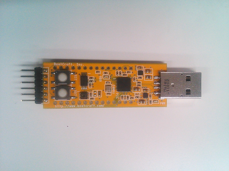
No pin headers are attached to BC-USB-Kit. There are only hole-throughs. Please solder a DIP-28 connected IC socket and an A/R type L-shaped 6-pin pin header to J1 and J2, respectively.
- In-Circuit Debugger
In-circuit Debugger is a tool for writing a firmware into a PIC micro controller. There are two types of In-Circuit Debuggers for PIC: MPLAB ICD 3 and MPLAB PICkit 3. In this article, PICkit 3 is used.
- Firmware (for checking)
The source code of a demo firmware, “USB Device - CDC - Sensors.zip,” is listed here. It uses the humidity and temperature sensor of BC-USB-Kit.
This firmware can be used for checking the operational status of BC-USB-Kit as well as testing this demo.
- MPLAB X ICD
This is an IDE for the PIC micro controller. It is used for developing firmwares.
- MPLAB XC Compilers 16bit version (XC16)
In this article, Windows version of MPLAB X IDE and MPLAB XC Compiler (XC16) are used.
If you use other platforms other than Windows, please apply the same kinds of tasks, which are explained here.
- Expand the downloaded source code of the firmware, “USB Device - CDC - Sensor.zip.”
- Start up X IDE.
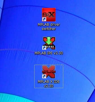
- From the menu of MPLAB X IDE, select File →Open Project...
Open Up “USB Device - CDC – Sensor.X,” which is located at the directory of “USB Device -CDC- Sensor\src\aps\usb\device\cdc_i2c\firmware\.”
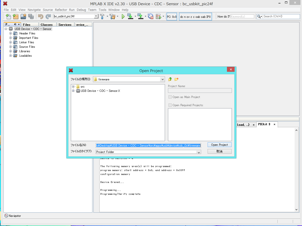
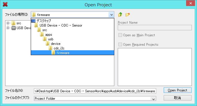
- Once open up the project you will use, close Start Page of MPLAB X IDE.
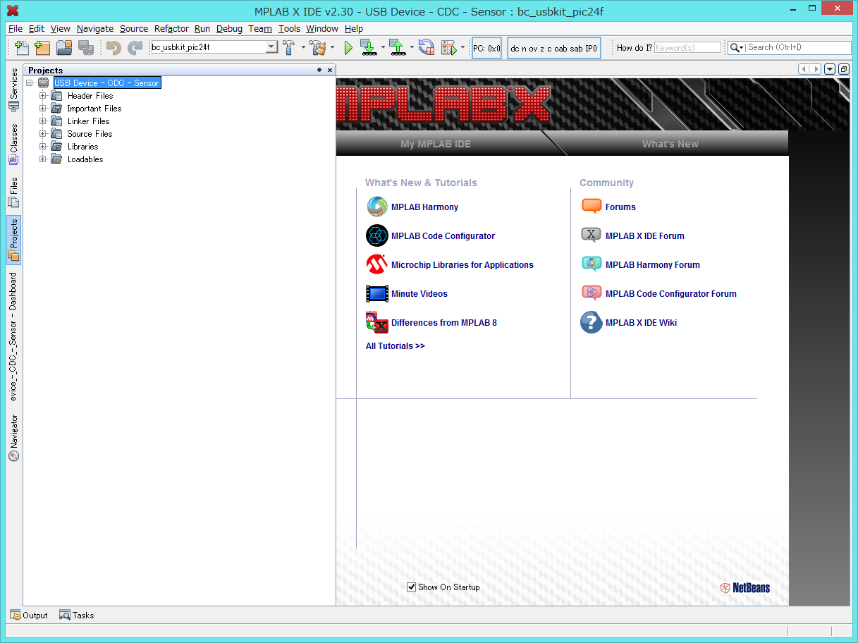
From the menu of MPLAB X IDE, choose Run →Set Project Configuration → Customize.
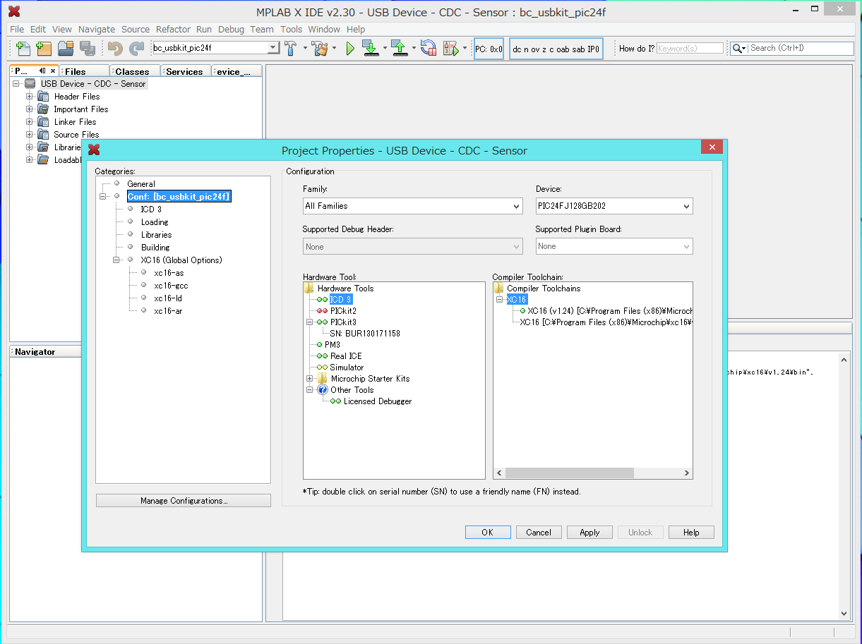
As the Project Properties Window opens, configure Hardware Tool and Compiler Toolchain for the project. In this project, PICkit 3 is selected for Hardware Tool, and XC16 (v.1.24) is chosen for Compiler Toolchain.
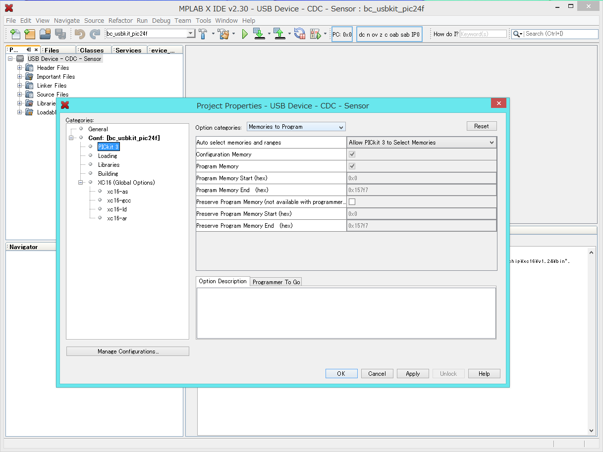
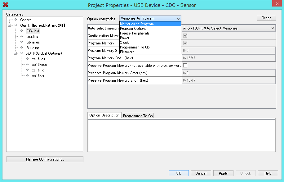
- Once these configurations of Hardware Tool and Compiler Toolchain are completed, select the configuration of Power for PICkit 3. Then, check the box of “Power target circuit form PICkit 3.” This is the end of preparations for building the firmware.
- Once the preparations are completed, to click the icon of Build Project (look at the red circle in the picture) on the window menu of MPLAB X IDE, execute the build process.
As the execution log shows up in the tab of USB Device - CDC - Sensor on Output pane, the build process of the firmware is completed.
The name of the built firmware is “USB_Device_-_CDC_-_Sensor.X.production.hex, which is located at the directory of “USB Device - CDC - Sensor\src\apps\usb\device\cdc_i2c\firmware\USB Device - CDC – Sensor.X\dist\bc_usbkit_pic24f\production.”
- The build process of the firmware is completed, click the icon of Run project (See the red circle in the picture) on the window menu of MPLAB X IDE.
The firmware is written into BC-USB-Kit by PICkit 3.
While PICkit 3 writes the firmware into PIC, the color of its status LED changes from green to red. As the writing process is completed without any issues, the color of status LED goes back from red to green.
The status of the writing process is appeared in the PICkit tab on Output pane of the MPLAB X IDE main window.
Programming...
Programming/Verify complete
When the status shown above appears in the tab, the writing process is successfully finished.
If you click the icon of Make and Program Device (See the red circle in the picture) on the window menu of MPLAB X IDE, both the build process and the writing process can be completed at once.
- If the writing process is failed, pull off the USB cable of PICkit 3 from the PC once and reconnect the USB cable to the PC. Then, at MPLAB X IDE, show the tab of “USB_Device_-_CDC_-_Sensor – Dashboard” on the left side pane of the main window, and click the icon of “Refresh Debug Tool Status.”
If the color of status LED at PICkit 3 turns to green, it means the system is working correctly.
Still the writing process is failed, please check the solder work at J2.
- 2015/04/01 This document is initially published.